Quantcast
Channel: Astro-Beano
Viewing all 33 articles
Browse latest View live

Widescreen upgrade for Birdbox 1

$
0
0
Over the weekend I upgraded my first Birdbox webcam to the improved design I used for the Woodpecker nest box camera, with a wide angle lens to capture the whole floor, and splayed IR LEDs to avoid whiteout/glare.
Xbox webcam original lens, forward IR LEDsXbox webcam, 2.8mm CCTV lens, splayed IR LEDs
During the upgrade I considered replacing the camera mounting in order to rotate the camera, but decided the confined box made it too much effort. With the new lens I can now capture the whole floor and some of the side walls - the view shifted slightly while reattaching the box to the wall - but it will do.

I don't expect a nest in the box this season now, but since Great Tit and spider visits and the wasp visit, I have had blue tits dropping in - two at once in fact! The combination of the small bird box and the standard Xbox webcam's lens meant a rather cropped view of the action - that and the lack of sound made it hard to be sure if this was a squabble or a pair:
I assume it was the same pair back the next morning:

I was pretty pleased with these shots, despite the 'white out' from the IR LEDs, but the framing was annoying me. One of the birds actually seemed to have a nap at the back of the box, almost completely off the bottom of the pictures. What I needed was a wider angle lens in this small bird box - and to splay the LEDs out (which I'd done on the three bird box cameras I'd setup since - improving the design as I learnt).

I recently bought and tested a set of CCTV board lens with the Xbox Live Vision webcam, but since that wide angle 2.8mm lens went into the woodpecker box, I bought another 2.8mm lens on eBay for this birdbox. This time the lens had a much shorter screw thread, and couldn't reach focus with the Xbox camera's mounting block. Therefore I replaced it with a taller mounting block from another webcamera (as explored in that post). For this purpose I don't want an IR filter on the block or lens, which was fortunate. Since the new lens is a different length and the original plastic cover wouldn't fit it, I used some blu-tack to seal the gap for moisture protection (and to stop the lens wobbling out of focus).

Fingers crossed for more visitors before too long, and that the motion webcam monitoring software will catch some more good pictures. Probably not of these two Blue Tits - I think they were looking a for a Plan B during the temporary Tree Sparrow invasion, but they are now nesting in Bird Box 3.

Update (24 April)

The new camera is working nicely - a sparrow visited this morning which was nice:

Unfortunately for the Blue Tits, the Sparrows have also been back inspecting Bird Box 3...

Targus USB 2.0 Micro Webcam

$
0
0
My Targus Micro Webcam just arrived a few weeks back - the link is for Amazon where it is currently £8, you can get at a similar price on Misco too, but I got lucky on eBay for just £4 while looking for an economical USB webcam with a USB based microphone. The Targus website says model number AVO05EU is now discontinued - so similar good deals might be available for a while.


According to the box this does 1280x1024 pixels (real 1.3 megapixels), and says "Ready to use; no drivers to install". That is usually a clue that you are dealing with a UVC webcam, and despite the "PC Only" label on the packaging, and it works fine under Mac OS X (both camera and the microphone). Here's what system_profiler SPUSBDataType says:

            USB 2.0 Camera:

              Product ID: 0x0332
              Vendor ID: 0x0ac8  (Z-Star Microelectronics Corporation)
              Version: 1.00
              Speed: Up to 480 Mb/sec
              Manufacturer: Vimicro Corp.
              Current Available (mA): 500
              Current Required (mA): 500

It came with a "Documentation Notice" which included the URL for the "User Guide", which was also included as a black & white leaflet. This and the label on the included base unit refer to it as Targus webcam model AVC05EU.

As you can tell from the shape, it is designed for use with a laptop, plugged into the side and then twisted to point at the user. However, I'm using it with a desktop (and my monitor lacks any handy side USB ports). I had to use the included stand which doubles as a USB extension cable. Sadly this won't balance on my monitor but it does the job:

I was looking for a webcam with a USB microphone to use on a Mac Pro which doesn't have a microphone-in socket, just an unamplified line-in. This works fine, so overall I'm happy with this purchase.

The only refinement would be somewhere to stick the USB cap when not in use - ideally on the webcam itself, or even on the stand. I'm not the first person to comment on this, and I won't be the first owner to lose the cap because of it!

Sparrows Nesting

$
0
0
After the disappointment of no residents in Bird Boxes 1 & 2, and the evicted blue tits in Bird Box 3, I was delighted to find Bird Box 4 in use - even if it wasn't by woodpeckers, but by sparrows. This was probably my favourite photo:


Rather than regular photos collected automatically, I was only able to check the camera periodically by taking a laptop down the garden - it was far beyond USB range.


Saturday 2 June

Little little birdies.Big mouthsHungry mouths

Tuesday 5 June

Just three days they have grown noticeably - with this shot you could hear excited chirping as the parent approached:

Dinner time!First served...We want more!

Saturday 9 June

Now two of the chicks seem noticeably bigger, and their wings look ready:

Three in a rowWaking upWhat can I see?
I want to see too!Just stretching...I'm still here

Sunday 10 June

They look ready to fledge now.

Who's the bravest?Who's the biggest?
Unhatched egg againNap time

Wednesday 13 June

And they've left home... probably under three weeks since hatching:

Empty nest
We can't be sure (as I suspect there are other sparrow broods in the area), but we've probably seen them since on the lawn being fed by their parents.

Raspberry Pi with two webcams

$
0
0
Provided they are plugged directly into the Raspberry Pi's two USB ports directly, I've been able to connect it to two web-cameras at once, and stream the pictures using the open source Motion software (which also records images for any movement). Watching a double webcam feed from Safari on my iPad, while controlling the Raspberry Pi using Panic Inc's SSH application Prompt was kind of fun!

As you might guess from past blog posts, I was trying (several) Microsoft Live Vision USB webcams, with the aim of using them via the RPi and a long ethernet cable to monitor my bird nesting box cameras. My plan (outlined back on this post) is to use power-over-ethernet (POE) to supply 5V to the Raspberry Pi, which will be down the garden within USB range of the birdbox or birdboxes. But first, to get this working indoors - which meant initially a long wait before my RPi was delivered.

Meanwhile, other people were also experimenting with using the RPi as an IP-webcam, like Jeremy who tried both ffserver on his RPi and then later switched to using Motion on a battery powered RPi webcam with wifi and more. Nice blog!

Motion under Raspbian

I decided to try the recently released Raspbian-based SD card image, specifically the 2012-07-15-wheezy-raspbian.zip release. During the first boot I used the menu to expand the file system to take the whole SD card, enabled SSH access, and set my keyboard and locale, and opted not to boot to the graphical desktop. I then ran an update, and installed Motion, the Apache webserver, Emacs, etc.

$ sudo apt-get update
$ sudo apt-get upgrade
$ sudo apt-get install motion
$ sudo apt-get install apache2
$ sudo apt-get install emacs

Initial experiments with an un-powered and a powered USB hub were not fruitful - the second webcam wouldn't register - in fact in some configurations even low power devices like my mouse or keyboard wouldn't work. So rather than trying this with a USB keyboard and mouse, I switched to SSH access and used the only two USB ports for two webcams - which worked.

$ ls /dev/vid*
/dev/video0  /dev/video1

I've already been running motion for a while now on an old laptop, so the configuration wasn't too hard - I knew that on my laptop getting several USB cameras running at once meant sticking with the default low resolution of 320x240 pixels. I went with two camera configuration files as ~/webcam/cam1.conf which is just:

videodevice /dev/video0
webcam_port 8081

And likewise for the second camera, configuration file ~/webcam/cam2.conf is just:

videodevice /dev/video1
webcam_port 8082

These are very short because everything else is in /etc/motion/motion.conf, the main configuration file, most of which remains with the default values. The main change is two thread settings pointing at the above per-camera settings:

webcam_localhost off
thread /home/pi/webcam/cam1.conf
thread /home/pi/webcam/cam2.conf

The only other configuration change so far is for making this act like an IP-webcam was to change the default (secure) setting restricting this to the same machine (local host). Note you must also ensure the two camera streams are on different ports (I went for the motion default of 8081, and 8082 for the second camera).

I then setup a minimal webpage by creating the file /var/www/webcam.html showing the two images side by side (which would be served by Apache). Initially I've just hard coded the RPi's hostname to access the two webcams, but I think a little Apache magic is a better solution considering my IP address is allocated by DHCP and will change, but this works for now.

Update: As requested in the comments, here's the simple HTML for the page I access as http://raspberrypi/webcam.html from within my home network (this should be edited if you change the default hostname of raspberrypi):

$ more /var/www/webcam.html
<html>
<head>
<title>Raspberry Pi Webcameras</title>
</head>
<body>
<h1>Raspberry Pi Webcameras</h1>
<a href="http://raspberrypi:8081/">

<img src="http://raspberrypi:8081/" alt="Camera 1" ></a>
<a href="http://raspberrypi:8082/">

<img src="http://raspberrypi:8082/" alt="Camera 2" ></a>
</body>
</html>


Update: If you want motion to auto-start when the computer is rebooted, you need to edit the file /etc/default/motion to say start_motion_daemon=yes and this will happen automatically via the /etc/init.d/motion startup script. I'm using this now that I have installed a Raspberry Pi in my garden. Note I added $all to the Required-Start list to hopefully ensure that the USB system, ethernet, and date-time (via the network) are live before starting Motion.

Data Sync

It would be nice if DropBox could run on the Raspberry Pi - but right now it doesn't. You can got here to vote for DropBox to support Linux on the ARM processor. That rules out one way to automatically collect movement triggered images from the RPi - but there are several other options here, perhaps rsync to a separate image server?

Update - More USB devices?

As I noted in the introduction, I could only get two USB webcams to work when directly connected - and thus had to log into the RPi by SSH to control it. Even trying two cameras and a keyboard via a powered or unpowered hub proved problematic.

Using a powered hub is the recommended solution, so perhaps my hub just wasn't up to the job? However, I've been reading about an alternative hack to bypass the RPi's F1 and F2 polyfuses as described on The IO BlogHimesh's blog, and elsewhere including this forum thread USB Port Current Boost. You would of course still need to use a sufficiently strong power supply.

Power Over Ethernet for Raspberry Pi

$
0
0
This weekend I tested powering my Raspberry Pi and two webcams via a simple passive Power Over Ethernet (PoE) adapter. Success! It was only a 2m ethernet cable, but I hope to use about 40m in order to set this up at the bottom of the garden to monitor the webcams in my bird boxes.
Raspberry Pi serving two webcams under Motion, 5V supplied by PoE

The main bit of equipment was a simple passive PoE kit bought on eBay for just £3. This comes in two parts, one with a female 2.1mm power connector to 'inject' power into the ethernet cable, and the other with a matching male 2.1mm power connector to 'split' the power back out. This is the same type of plug commonly used for CCTV cameras, and indeed the power supply for my EQ2 Telescope motor (although those don't use just 5V).
PoE female power injectorPoE male power out

I supplemented this with a matching 2.1mm male (Maplins part HH60Q) and female power adapter (Maplins part JK11M), plus solder and a soldering iron coming to just over £10. With hindsight, several years absence had not improved my soldering skill, and I'd have been better off spending the money on some of the solder-free solutions available on the Maplins website.

The final part of this was a male USB-mirco plug to connect the power supply to the RPi. Maplins don't sell these (and soldering one would be beyond my skill anyway), so took my perfectly good 5V mains adapter to micro-USB power supply (bought with the RPi), and butchered it. Then I managed to solder the 2.1mm female socket to the USB-micro plug, at least well enough for the test in the photo above.

The setup works as follows: Mains --> 5V power power adapter --> 2.1mm plug --> Ethernet injector --> Ethernet cable --> Ethernet splitter --> 2.1mm plug --> USB micro --> Raspberry Pi.

Update - Longer cable, 40m

The PoE kit did say it should work up to 30m, but I tried it with a 40m ethernet cable anyway. I was expecting quite a voltage drop, so with the supply at 5V getting just a weak little red glow from the RPi power LED wasn't a surprise. Using my variable voltage adapter I tried increasing this to 6V, then 7.5V, and 9V. These were enough to get a healthy brightness from the PRi's power LED, and without the webcams enough to light the green OK LED too, but not enough for it to boot up. I'll see if I can find my volt meter, or borrow one, to see what exactly is reaching the RPi. Perhaps while the voltage is enough, the current is too low? I'm a little nervous about trying any higher input voltage without taking measurements though!

Update - Medium cable, 30m

I was more hopeful for this cable, and with a 5V input the RPi's red power LED was quite bright - but still didn't boot up and connect to the network. Nor would it with 6V or 7.5V, even without the webcams. However I did try connecting it to my TV with the HDMI out, and realised that the flashing green OK LED meant it had actually booted up - but for whatever reason hadn't connected to the network.

So I was tempted, and stepped it up to 9V input to the passive PoE, and had some success with no external USB devices. It wasn't at all stable, but the RPi did manage to connect to my network for short moments. Watching the boot log on screen it was clear that the ethernet adapter itself is USB based (confirmed online), and it was connecting/disappearing as a USB device. My assumption is there isn't quite enough power getting through.

I think I should find/replace my electrical meter before pushing my luck any further - the next setting on this power supply is 12V, and that seems quite a risk.

If anyone is interested, I've been using a Maplin Low Power Multi-Voltage Desktop Power Supply - model VN10L . The claimed output is 2.5A at 5V/6V, 2A at 7.5V, and 1.7A at 9V/12V, and 1.5A at the maximum 13.2V setting.

Update (9 September 2012)

I found my voltage meter, so was able to measure the actual voltage reaching the Raspberry Pi using the TP1 and TP2 connections (test points one and two, down from the logo and by the yellow video out jack respectively). This confirmed what I was hoping - I just hadn't been brave enough till now about ramping up the input voltage :)

Using no external USB devices (and no monitor), giving the power via the 30m ethernet cable, I found the input of 9V was reaching the RPi as about 4.8V, just about enough to power up the ethernet. Upping the input to 12V gave the RPi more than enough - it wobbled around 7.1V but the network worked.

Using the 30m ethernet with one USB web camera, 9V input was not enough. However, either the 12V input (measured as about 5.3V) or 13.5V input (measured as about 6V) worked fine and I could stream the image (not a great frame rate, but it works).

Using the 30m ethernet with two USB webcams physically connected, I had to use the maximum 13.5V from my supply to boot with ethernet, but only one camera would work. The measured voltage seemed to wobble from 4.2V to almost 7V, probably linked to the total USB activity.

So - success at 30m - with some potential room for improvement if I want to try and monitor two cameras at once (although I know this will give a poor frame rate). I've now also got a DC/DC step down converter to try (mentioned in the comments below), and there is also the option of removing (or bridging to bypass) the resetable fuses protecting the Raspberry Pi's USB outputs - which has been reported to help with power hungry USB devices (herehere and elsewhere). Reassuringly, these fuses have been removed in the recently announced Raspberry Pi revision 2.0 board.

Update (16 September 2012)

Here are a couple of photos from field testing with the 30m cable, actually at the bottom of the garden connected to the camera in Birdbox 3. It took me a while to relocate the secondary router, but as a bonus my wifi signal now extends far enough for an in situ test with my iPod touch showing the live feed from the Raspberry Pi.
Spare birdbox with Raspberry Pi in itLive nestbox webcam test!

Unfortunately the 30m cable only just reaches this spot, so I'll need to get this to work with my 40m ethernet cable...

Update (2 October 2012)

Trying this with a 12V to 5V DC step-down didn't seem to help, but powering the Raspberry Pi with 24V passive POE works at 40m (indoor testing).

Update (30 Jan 2013)

Successful 40m outdoor 24V passive POE Raspberry Pi installation.

ChipsBnk USB SD card reader

$
0
0
Last month bought an SDHC USB adapter (£1.75) and a triple set of own-brand 8GB Class 10 SD cards (£12.99) from 7dayshop.com claiming to support up to 20MB/s. One card wouldn't even mount but found this open source tool (for Linux or Mac) very useful to test the remaining memory cards: Michel Machado's F3 (repository on github).


The good news was that the USB adapter seemed to work fine on my exiting battle tested 8GB SD cards - but the trouble started with the new 7dayshop branded cards:


Card One - Bust?

$ system_profiler SPUSBDataType
...

            USB Reader:

              Product ID: 0x4082
              Vendor ID: 0x1976
              Version: 1.00
              Serial Number: 110074973765
              Speed: Up to 480 Mb/sec
              Manufacturer: ChipsBnk
              Location ID: 0xfa130000 / 6
              Current Available (mA): 500
              Current Required (mA): Unknown (Device has not been configured)

I waited a bit longer and then it could tell me about the card inserted,


            USB Reader:

              Capacity: 1.07 GB (1,073,741,824 bytes)
              Removable Media: Yes
              Detachable Drive: Yes
              BSD Name: disk1
              Product ID: 0x4082
              Vendor ID: 0x1976
              Version: 1.00
              Serial Number: 110074973765
              Speed: Up to 480 Mb/sec
              Manufacturer: ChipsBnk
              Location ID: 0xfa130000 / 6
              Current Available (mA): 500
              Current Required (mA): 100
              Partition Map Type: Unknown
              S.M.A.R.T. status: Not Supported

That looks like 1GB, despite the sticker saying 8GB. I waited a bit longer, and the adapter's red LED stayed on solid - and then it doesn't show up in the USB devices at all. And the card never showed up in finder. Grr. It wouldn't work in my camera either.

Card Two

This looked OK,

            USB Reader:

              Capacity: 8.07 GB (8,072,986,624 bytes)
              Removable Media: Yes
              Detachable Drive: Yes
              BSD Name: disk1
              Product ID: 0x4082
              Vendor ID: 0x1976
              Version: 1.00
              Serial Number: 110074973765
              Speed: Up to 480 Mb/sec
              Manufacturer: ChipsBnk
              Location ID: 0xfa130000 / 6
              Current Available (mA): 500
              Current Required (mA): 100
              Partition Map Type: MBR (Master Boot Record)
              S.M.A.R.T. status: Not Supported
              Volumes:
                NO NAME:
                  Capacity: 8.07 GB (8,068,792,320 bytes)
                  Available: 8.06 GB (8,062,304,256 bytes)
                  Writable: Yes
                  File System: MS-DOS FAT32
                  BSD Name: disk1s1
                  Mount Point: /Volumes/NO NAME
                  Content: DOS_FAT_32

Card Three

            USB Reader:

              Capacity: 8.07 GB (8,072,986,624 bytes)
              Removable Media: Yes
              Detachable Drive: Yes
              BSD Name: disk1
              Product ID: 0x4082
              Vendor ID: 0x1976
              Version: 1.00
              Serial Number: 110074973765
              Speed: Up to 480 Mb/sec
              Manufacturer: ChipsBnk
              Location ID: 0xfa130000 / 6
              Current Available (mA): 500
              Current Required (mA): 100
              Partition Map Type: MBR (Master Boot Record)
              S.M.A.R.T. status: Not Supported
              Volumes:
                NO NAME:
                  Capacity: 8.07 GB (8,068,792,320 bytes)
                  Available: 688 KB (688,128 bytes)
                  Writable: Yes
                  File System: MS-DOS FAT32
                  BSD Name: disk1s1
                  Mount Point: /Volumes/NO NAME
                  Content: DOS_FAT_32

Wow - capacity 8GB, but only 688KB available? Turned out it had several *.h2w files on it suggesting it had been tested with the Windows H2testw - perhaps by a previous customer who sent it back? So, I tried out the tool F3, having first renamed the card to help keep track of things:

$ git clone https://github.com/AltraMayor/f3.git
...
$ cd f3
$ make mac
...

Then use f3write to fill up the card with test files,

$ ./f3write /Volumes/7DayShop3/
Free space: 7.51 GB
Creating file 0001.fff ... OK!                      
Creating file 0002.fff ... OK!                      
Creating file 0003.fff ... OK!                      
Creating file 0004.fff ... OK!                      
Creating file 0005.fff ... OK!                      
Creating file 0006.fff ... OK!                      
Creating file 0007.fff ... OK!                      
Creating file 0008.fff ... OK!                    
Free space: 0.00 Byte
Average writing speed: 8.76 MB/s

Now use these test files to check reading the data back works:

$ ./f3read /Volumes/7DayShop3/

                     SECTORS      ok/corrupted/changed/overwritten
Validating file 0001.fff ... 2097152/        0/      0/      0
Validating file 0002.fff ... 2097152/        0/      0/      0
Validating file 0003.fff ...  335488/        0/      0/      0Assertion failed: (*read_all || errno == EIO), function validate_file, file f3read.c, line 126.
Abort trap: 6

Then it was unmounted, with a red exclamation error dialogue popping up warning the disk was not ejected properly. I remove the adapter, reinserted it, and tried again:

$ ./f3read /Volumes/7DayShop3/
                     SECTORS      ok/corrupted/changed/overwritten
Validating file 0001.fff ... 2097152/        0/      0/      0
Validating file 0002.fff ... 2097152/        0/      0/      0
Validating file 0003.fff ... 2097152/        0/      0/      0
Validating file 0004.fff ... 2097024/      128/      0/      0
Validating file 0005.fff ... 1660288/        0/      0/      0Assertion failed: (*read_all || errno == EIO), function validate_file, file f3read.c, line 126.
Abort trap: 6

Same problem - plus f3read detected some corruption.  The third attempt failed even quicker:

$ ./f3read /Volumes/7DayShop3/
                     SECTORS      ok/corrupted/changed/overwritten
Validating file 0001.fff ... 1987584/        0/      0/      0Assertion failed: (*read_all || errno == EIO), function validate_file, file f3read.c, line 126.
Abort trap: 6

From later experience these disconnections are probably down to the USB card reader - but f3read did spot corruption in file four above.

Card Two

I decided to run the tests on the apparently good card as well, writing seemed OK:


$ ./f3write /Volumes/7DayShop2
Free space: 7.51 GB
Creating file 0001.fff ... OK!                        
Creating file 0002.fff ... OK!                        
Creating file 0003.fff ... OK!                        
Creating file 0004.fff ... OK!                        
Creating file 0005.fff ... OK!                      
Creating file 0006.fff ... OK!                      
Creating file 0007.fff ... OK!                      
Creating file 0008.fff ... OK!                      
Free space: 0.00 Byte
Average writing speed: 7.75 MB/s

So did reading:

$ ./f3read /Volumes/7DayShop2
                     SECTORS      ok/corrupted/changed/overwritten
Validating file 0001.fff ... 2097152/        0/      0/      0
Validating file 0002.fff ... 2097152/        0/      0/      0
Validating file 0003.fff ... 2097152/        0/      0/      0
Validating file 0004.fff ... 2097152/        0/      0/      0
Validating file 0005.fff ... 2097152/        0/      0/      0
Validating file 0006.fff ... 2097152/        0/      0/      0
Validating file 0007.fff ... 2097152/        0/      0/      0
Validating file 0008.fff ... 1067328/        0/      0/      0

  Data OK: 7.51 GB (15747392 sectors)
Data LOST: 0.00 Byte (0 sectors)
      Corrupted: 0.00 Byte (0 sectors)
Slightly changed: 0.00 Byte (0 sectors)
    Overwritten: 0.00 Byte (0 sectors)
Average reading speed: 16.64 MB/s

Conclusion

One out of three cards seems to be OK. Not good - but I got to test the 7dayshop customer service, who refunded the cards without any hassle. Having been stung by this I bought some main stream brand SDHC cards instead.

I decided to keep the card reader, but in usage since I've found the card reader not 100% reliable - e.g. it would disconnect while copy photos off an SD card. For that job I've continued to use my camera directly via its USB cable. The card reader would also disconnect while running f3read on my 'good' memory cards.

However, I was able to use the reader to create a bootable image to use on my Raspberry Pi on another SDHC card - which was the main reason I bought it anyway - so I feel I got my £1.75 worth of usage from it ;)

24V passive POE for Raspberry Pi

$
0
0
Today my 24V power supply arrived - the final part I needed to try a 24V passive power-over-ethernet (POE) solution down a 40m cable to drive my Raspberry Pi and two webcams. Good news - it works!
Raspberry Pi and two Xbox Live Vision webcams
using 24V passive power over ethernet (POE)

I'd previously succeeded in running two webcams directly from the Raspberry Pi (when mains powered), and managed to run one webcam from RPi using 12V passive POE over 30m - but that cable only just reached the bird box with camera at the end of the garden so I wanted a longer network cable. I searched the house for stronger power supplies,  giving two different flat screen monitor 12V DC supplies a go - but had no joy at 40m (even without the cameras).

The only thing for it was more volts! And 24V seemed the way to go. While waiting for the parts to arrive, I realised I'd hit on the same idea as plugwash's ghetto POE solution on the Raspberry Pi Forums - also highlighted by Frambozenbier.

I ordered an adjustable 24V to 5V DC-DC step-down unit from eBay for a few pounds, searching specifically for a KIS-3R33s based unit based on advice I'd read online. The claimed specifications for anyone wanting to buy something similar were:
  • IS-3R33S integrated with adjustable MOSFET MP2307DN
  • Size: 45mm by 32mm
  • Input voltage: 4.75-24V
  • Output voltage: 0.93V-18V
  • Efficiency: up to 98%
  • Output current: rated 3A, max up to 4A peak 
  • Programmable Soft-Start
  • Low ESR Ceramic capacitors is recommended at output
  • Internal Frequency: Fixed 340kHz
  • Output ripple: 20M bandwidth (for reference only)
  • Protection: Cycle-by-cycle over current protection.
The rubbery coating on mine didn't look too good, but it works OK. Notice the small screw on the blue block between the large orange capacitors - that controls the output voltage:

KIS-3R33S based DC step-down

I attached this to a couple more  2.1mm  barrel connectors from Maplins for ease of use - given that's what the rest of my setup uses:
More DIY soldering to add connectors

A quick reminder image from my previous blog post - the simple £3 passive PoE kit from eBay:
PoE female power injectorPoE male power out

Surprisingly Maplins didn't have any 24V DC supplies in store, so again I turned to eBay and ordered a 24V 1200mA power supply (aiming for a reasonable power rating), which was the last part to arrive.

Initially I set the DV output to 5.25V to match what the original power supply I'd used gave. That worked but under load this fell to just 4.8V, so by fine tuning the DC step-down converter I could ensure the the Raspberry Pi was getting the full 5V it wants even with the two web cameras attached.

The setup works as follows: Mains --> 24V power power adapter --> 2.1mm plug --> Ethernet injector --> 40m Ethernet cable --> Ethernet splitter --> 2.1mm plug --> 24V:5V step down --> USB micro --> Raspberry Pi --> USB --> Webcameras.

The observant may wonder why the green LEDs on the Xbox Live Vision web cameras are not on - that's because I've disabled them for astro-photography and use in a bird nesting box (the camera on the right has four infra-red LEDs added to it).

My next project will be to install the Raspberry Pi and voltage step-down module in a suitably water tight container to mount in the garden, and run the 40m ethernet cable to it. Then I should finally be able to monitor the bird box remotely.

Update: Successful indoors testing.

Update: Successful outdoor testing.

Pharos/Microsoft GPS-360 on Raspberry Pi

$
0
0
I bought a Microsoft GSP-360 USB dongle on eBay as an impulse purchase, toying with the idea of running a Raspberry Pi in my car for live map display or at least route tracking for contributing road traces to the Open Street-Map project. Just getting my location out of it proved harder than I'd expected.

The front of the dongle has a big Microsoft logo, while the sticker on the back (which has a bright blue LED when active) says:
P/N: X11-49577
360-1000-02
S/N: ...
GPS-360
Tested to comply with FCC standards
Rating: DC 3.5 - 5.5V 70mA
Pharos USA
SiRF Powered
Made in China
For running this with a Raspberry Pi that current information could be useful, and the broad voltage tolerance is reassuring. What do we learn at the command line? It appears as a Profilic USB/Serial adaptor at the USB level - here's what my Mac tells me:

$ system_profiler SPUSBDataType
...
            USB-Serial Controller:

              Product ID: 0xaaa0
              Vendor ID: 0x067b  (Prolific Technology, Inc.)
              Version: 3.00
              Serial Number: 12345678
              Speed: Up to 12 Mb/sec
              Manufacturer: Prolific Technology Inc.
              Location ID: 0xfa130000 / 6
              Current Available (mA): 500
              Current Required (mA): 500

And in Linux, running on a Raspberry Pi (with no other devices attached):

$ lsusb 
Bus 001 Device 001: ID 1d6b:0002 Linux Foundation 2.0 root hub
Bus 001 Device 002: ID 0424:9512 Standard Microsystems Corp. 
Bus 001 Device 003: ID 0424:ec00 Standard Microsystems Corp. 
Bus 001 Device 004: ID 067b:aaa0 Prolific Technology, Inc. Prolific Pharos


USB/Serial Drivers

I should be able to talk to the USB-serial port, but to do on the Mac it seems I must first install a Prolific USB-serial driver. That's what this and this helpful blog told me.  Finding the Prolific USB/serial driver for Mac OS X took a while, it was hiding behind a "GUEST"/"GUEST" password protected page - but I eventually found md_PL2303_MacOSX10.6_dmg_v1.4.0.zip released 2011/05/13 which claims to support OS X 10.8 Mountain Lion. There's also an open source driver, osx-pl2303 on SourceForge (SVN latest updated Jan 2008), forked as osx-pl2303 on Github (last updated Nov 2011), reported to have been tested under Mac OS X 10.7 Lion and 10.8 Mountain Lion. I punted on this.

As an aside, finding drivers for older versions of Windows was quite easy, but Profilic won't support their older PL-2303HXA and PL-2303X chips under Windows 8, using this as a stick to encourage people to buy their newer PL2303TA chip instead. Ouch.

For Linux there drivers should be already installed - so I went with that. Here's an excerpt from the Raspberry Pi boot log (with the GSP-360 dongle as the only external USB device plugged in):

$ dmseg
...
[   38.098548] usb 1-1.3: new full-speed USB device number 4 using dwc_otg
[   38.200535] usb 1-1.3: New USB device found, idVendor=067b, idProduct=aaa0
[   38.200565] usb 1-1.3: New USB device strings: Mfr=1, Product=2, SerialNumber=3
[   38.200581] usb 1-1.3: Product: USB-Serial Controller
[   38.200595] usb 1-1.3: Manufacturer: Prolific Technology Inc.
[   38.200608] usb 1-1.3: SerialNumber: 12345678
[   38.270238] usbcore: registered new interface driver usbserial
[   38.272087] USB Serial support registered for generic
[   38.273859] usbcore: registered new interface driver usbserial_generic
[   38.273887] usbserial: USB Serial Driver core
[   38.283343] USB Serial support registered for pl2303
[   38.283511] pl2303 1-1.3:1.0: pl2303 converter detected
[   38.290249] usb 1-1.3: pl2303 converter now attached to ttyUSB0
[   38.291944] usbcore: registered new interface driver pl2303
[   38.291972] pl2303: Prolific PL2303 USB to serial adaptor driver

As per that log, the new serial port is available as /dev/ttyUSB0

$ ls -l /dev/ttyUSB0 
crw-rw---T 1 root dialout 188, 0 Oct 11 15:57 /dev/ttyUSB0

I'm using the default image here, username 'pi', and I am therefore a member of the dialout group so should be able to connect to this device:

$ groups
pi adm dialout cdrom sudo audio video plugdev games users input

Strangely I didn't (immediately) get anything from the device using a low level check:

$ cat /dev/ttyUSB0
(nothing)


GPSD

It seems the main low-level GPS software for Linux is gpsd, so I installed that and tried to run it.

$ sudo apt-get install gpsd gpsd-clients
...

Encouragingly the GPSD hardware page says support for the Microsoft GPS-360 is good, they test it before each release, and it should be plumbed into the Linux hotplug system to start gpsd automatically.

Rebooting with the GPS attached should create /dev/gps0 as an alias for /dev/ttyUSB0 and start the gpsd daemon automatically, check with:

$ ps -e | grep gpsd
  307 ?        00:00:00 gpsd

In this case it is running (with process identifier 307). Similarly, if you boot up without the dongle and then plug it in, it should be recognised as gpsd started automatically. If it is running, this should kill it (advice from the GPSD Troubleshooting page):

$ sudo killall gpsd
$ sudo rm /var/run/gpsd.sock

You can (re)start it manually with:

$ gpsd /dev/ttyUSB0 

I then tried a little test (with the daemon off):

$ gpsctl -f -n /dev/ttyUSB0
gpsctl:SHOUT: vendor/product match with 091e:0003 not found
gpsctl:ERROR: packet recognition timed out.

That isn't good... the -f meant without using the deamon mode of gpsd, the -n meant switch to NMEA mode. When it works I got this and could look at the raw NMEA output:

$ gpsctl -f -n /dev/ttyUSB0
gpsctl:SHOUT: vendor/product match with 091e:0003 not found
gpsctl:SHOUT: /dev/ttyUSB0 identified as a SiRF binary at 4800.
gpsctl:SHOUT: switching to mode NMEA.

$ cat /dev/ttyUSB0 
$GPGGA, ...

Incidentally, until I read this blog post about why GSP support sucks, I'd been under the impression that NMEA 0183 was a good standard.

The GPSD Troubleshooting suggests starting with xgps or cgps. When cgps works:

$ cgps
┌───────────────────────────────────────────┐┌─────────────────────────────────┐
│    Time:       2012-10-11T17:06:42.920Z   ││PRN:   Elev:  Azim:  SNR:  Used: │
│    Latitude:    56.XXXXXX N               ││   1    XX    XXX    XX      Y   │
│    Longitude:    3.XXXXXX W               ││  11    XX    XXX    XX      Y   │
│    Altitude:   58.9 m                     ││  32    XX    XXX    XX      Y   │
│    Speed:      1.4 kph                    ││  20    XX    XXX    XX      Y   │
│    Heading:    215.3 deg (true)           ││  14    XX    XXX    XX      Y   │
│    Climb:      12.8 m/min                 ││  28    XX    XXX    XX      Y   │
│    Status:     3D FIX (3 secs)            ││  19    XX    XXX    XX      Y   │
│    Longitude Err:   +/- 10 m              ││  17    XX    XXX    XX      Y   │
│    Latitude Err:    +/- 11 m              ││  11    XX    XXX    XX      Y   │
│    Altitude Err:    +/- 32 m              ││                                 │
│    Course Err:      n/a                   ││                                 │
│    Speed Err:       +/- 84 kph            ││                                 │
│    Time offset:     0.509                 ││                                 │
│    Grid Square:     IO86kk                ││                                 │
└───────────────────────────────────────────┘└─────────────────────────────────┘
{"class":"DEVICES","devices":[{"class":"DEVICE","path":"/dev/ttyUSB0","activated":"2012-10-11T17:06:39.461Z","flags":1,"driver":"SiRF binary","subtype":...

I've masked out my exact location. Note CPU usage running gpsd and cgps with the default SiRF binary protocol was about 8%.

However, after rebooting and immediately running cgps it starts, waits for a bit with missing location information, then quits with a time out:

$ cgps
┌───────────────────────────────────────────┐┌─────────────────────────────────┐
│    Time:       n/a                        ││PRN:   Elev:  Azim:  SNR:  Used: │
│    Latitude:   n/a                        ││                                 │
│    Longitude:  n/a                        ││                                 │
│    Altitude:   n/a                        ││                                 │
│    Speed:      n/a                        ││                                 │
│    Heading:    n/a                        ││                                 │
│    Climb:      n/a                        ││                                 │
│    Status:     NO FIX (0 secs)            ││                                 │
│    Longitude Err:   n/a                   ││                                 │
│    Latitude Err:    n/a                   ││                                 │
│    Altitude Err:    n/a                   ││                                 │
│    Course Err:      n/a                   ││                                 │
│    Speed Err:       n/a                   ││                                 │
│    Time offset:     n/a                   ││                                 │
│    Grid Square:     n/a                   ││                                 │
└───────────────────────────────────────────┘└─────────────────────────────────┘
{"class":"WATCH","enable":true,"json":true,"nmea":false,"raw":0,"scaled":false,"timing":false}
cgps: GPS timeout

I also ran into this:

$ gpsctl -n /dev/ttyUSB0
gpsctl:ERROR: error 'Multiple subscribers, cannot change control bits on /dev/ttyUSB0.'
gpsctl:ERROR: /dev/ttyUSB0 mode change to NMEA failed

And:

$ cat /dev/ttyUSB0 
cat: /dev/ttyUSB0: Device or resource busy

I'm not quite sure what is going on here. I suspect a problem in how gpsd is started automatically (possibly Debian or Raspian specific?). What does seem to work is a cold restart (from power off) with the dongle attached, log in, kill and restart gpsd, and then run cgps.


GPS Babel

The  Open Street-Map on their instructions for uploading GPS tracks request GPX format and recommend GPS Babel to generate this. At the time of writing the latest release is GPSBabel 1.4.4, the repository hasn't caught up yet as this gave me v1.4.3:

$ sudo apt-get install gpsbabel
...

$ gpsbabel -V

GPSBabel Version 1.4.3

Then (provided that everything was co-operating - see above), I could use the gpsd utility to switch the output to NMEA mode, capture some of that to a file, and convert it into GPX format using gpsbabel:

$ gpsctl -f -n /dev/ttyUSB0
gpsctl:SHOUT: vendor/product match with 091e:0003 not found
gpsctl:SHOUT: /dev/ttyUSB0 identified as a SiRF binary at 4800.
gpsctl:SHOUT: switching to mode NMEA.
$ cat /dev/ttyUSB0 
$GPGGA,...
^C
$ cat /dev/ttyUSB0 > temp.nmea
^C
$ gpsbabel -i nmea -f temp.nmea -o gpx -F temp.gpx
$ head temp.gpx 
<?xml version="1.0" encoding="UTF-8"?>
<gpx
  version="1.0"
  creator="GPSBabel - http://www.gpsbabel.org"
  xmlns:xsi="http://www.w3.org/2001/XMLSchema-instance"
  xmlns="http://www.topografix.com/GPX/1/0"
  xsi:schemaLocation="http://www.topografix.com/GPX/1/0 http://www.topografix.com/GPX/1/0/gpx.xsd">
<time>2012-10-11T18:17:34Z</time>
<bounds minlat="56.xxxxxxxxx" minlon="-3.xxxxxxxxx" maxlat="56.xxxxxxxxx" maxlon="-3.xxxxxxxxx"/>
<trk>

In principle that should work with the SiRF binary format, but perhaps something is going wrong when I try to capture a random section with since the GPX file is essentially empty (valid XML, but no actual data unlike the NMEA capture above):

$ gpsctl -f /dev/ttyUSB0
gpsctl:SHOUT: vendor/product match with 091e:0003 not found
gpsctl:SHOUT: /dev/ttyUSB0 identified as a SiRF binary at 4800.
$  cat /dev/ttyUSB0 > temp.sbn 
^C
$ gpsbabel -i sbn -f temp.sbn -o gpx -F temp.gpx
$ more temp.gpx 
<?xml version="1.0" encoding="UTF-8"?>
<gpx
  version="1.0"
  creator="GPSBabel - http://www.gpsbabel.org"
  xmlns:xsi="http://www.w3.org/2001/XMLSchema-instance"
  xmlns="http://www.topografix.com/GPX/1/0"
  xsi:schemaLocation="http://www.topografix.com/GPX/1/0 http://www.topografix.com/GPX/1/0/gpx.xsd">
<time>2012-10-11T18:25:47Z</time>
</gpx>

That was rather tortuous. But with the rough edges sorted out could work as the basis of a GPS track logger.

Update

Here's a link to Peter Mount's blog post using a GPS dongle and Raspberry Pi as an NTP server (Network Time Protocol), useful as a way to set the clock on a RPi as it has no internal battery like a normal PC - meaning it needs a network connection or other external system to set the time and date. It seems he is also wondering about connecting his Raspberry Pi to his telescope...

Update

Here's a link to David Taylor's GSP based Raspberry Pi NTP server page, incredibly detailed including how to use Pulse Per Second (PPS) for improved precision.

Navit GPS on Raspberry Pi

$
0
0
I've got a USB GPS dongle working with my Raspberry Pi, so I started exploring mapping software that I could run on it if I were to mount the RPi in my car with a little screen - the simple low resolution screens used for reverse parking cameras sold on eBay for under £20 look perfect.

Two options came up, GpsDrive and Navit - both of which recommend map data from Open StreetMap. Of these only Navit is available in the Debian/Raspian repository, so I tried that first.

$ sudo apt-get install gpsd gpsd-clients navit


Since Navit is a graphical tool, you'll either need to run with a screen attached, or ssh in with X forwarding and display Navit on your computer. I did the later, there is hardly any GPS signal where our TV is, and I don't yet have any other suitable screen.

Assuming gpsd is working and you're getting a good location from the GPS, when running Navit for the first time you get a black screen with a little green circle for your location - since it doesn't come with any useful maps pre-loaded.

Installing a Map

I followed the wiki links to the Navit Planet Extractor website, drilled down through the menu of pre-defined areas, picked Scotland, and waited for the map file to download. I then copied this to my RPi, and put it in a maps folder with a more meaningful name:

$ mkdir maps
$ mv osm_bbox_-8.1,54.5,-0.1,61.4.bin maps/osm_Scotland.bin

Referring to their Navit configuration instructions, I need to start by creating a configuration file based on the template provided, and then added the new map to it:

$ cp /etc/navit/navit.xml ~/.navit/navit.xml
$ sudo apt-get install emacs
$ emacs ~/.navit/navit.xml


Scanning the example configuration you come to a OpenStreetMap example entry:

                <!-- Mapset template for openstreetmaps -->
                <mapset enabled="no">
                        <map type="binfile" enabled="yes" data="/media/mmc2/MapsNavit/osm_europe.bin"/>
                </mapset>


So I copied that, switched it to enabled="yes", and pointed it at my new Scotland map file:


                <!-- Mapset template for openstreetmaps -->
                <mapset enabled="yes">
                        <map type="binfile" enabled="yes" data="/home/pi/maps/osm_Scotland.bin"/>
                </mapset>


I also disabled the sample map. Next time I ran Navit, I saw this at the terminal, and a map on screen:

navit:main_real:Using config file '/home/pi/.navit/navit.xml'

Navit on Raspberry Pi showing Dundee using OpenStreetMap
Using the arrow keys moves the map. Pressing enter brings up a menu, again use the cursor keys to move, and escape goes back. Selecting the menu "Settings",  "Maps", I could check it was looking at my new file. You can also control various things like orient the map North via the GUI, and switch the display mode (e.g. bright or for night driving). The proper way to shutdown Navit seems to be selecting the menu "Actions", "Quit".

Since this Scotland map was only 126MB, I decided to download the entire British Isles. Using the mouse on the Navit Planet Extractor website I picked bottom left (49.5, -11.2) and top right (61.1, 3.0), giving a 441MB file instead.

There is in fact a Navit world map available, at the time of writing 9.2GB in size (which would fit fine on a 16GB SDHC card if I really wanted to use it).

Building Navit from SVN

At this point I wondered if I could build Navit on the Raspberry Pi (see Navit on Linux instructions) from their SVN repository (recommended on their website), as the Raspbian package is already quite dated. Getting the build dependencies the easy way failed:

$ sudo apt-get build-dep navit
Reading package lists... Done
Building dependency tree       
Reading state information... Done
E: You must put some 'source' URIs in your sources.list

Seems a little configuration is needed perhaps? Having played with apt-rdepends, this seems to work instead - perhaps overkill:

$ sudo apt-get install subversion espeak cmake freeglut3-dev imagemagick libdbus-1-dev libdbus-glib-1-dev libdevil-dev libfontconfig1-dev libfreetype6-dev libfribidi-dev libgarmin-dev libglc-dev libgps-dev libgtk2.0-dev libimlib2-dev libpq-dev libqt4-dev libqtwebkit-dev librsvg2-bin libsdl-image1.2-dev libspeechd-dev libxml2-dev ttf-liberation

And now the build - the output from cmake looked good, make itself took half an hour on the RPi:

pi@raspberrypi ~ $ mkdir repositories
pi@raspberrypi ~ $ cd repositories
pi@raspberrypi ~/repositories $ sudo apt-get install cmake subversion build-essentials
pi@raspberrypi ~/repositories $ svn co https://navit.svn.sourceforge.net/svnroot/navit/trunk/navit/ navit
pi@raspberrypi ~/repositories $ cd navit
pi@raspberrypi ~/repositories/navit $ mkdir build
pi@raspberrypi ~/repositories/navit $ cd build
pi@raspberrypi ~/repositories/navit/build $ cmake ..
pi@raspberrypi ~/repositories/navit/build $ time make

The docs tell you to run this in place. We also have to update this configuration file as discussed above to use the new map:

pi@raspberrypi ~/repositories/navit/build $ cd navit/
pi@raspberrypi ~/repositories/navit/build/navit $ emacs navit.xml
pi@raspberrypi ~/repositories/navit/build/navit $ ./navit
Running from source directory
vehicle_gpsd:vehicle_gpsd_try_open:Trying to connect to localhost:default
vehicle_gpsd:vehicle_gpsd_try_open:Connected to gpsd fd=5 evwatch=0x1c6f30
navit:vehicle_ref:refcount 2
navit:vehicle_unref:refcount 1
navit:main_real:Using config file '/home/pi/repositories/navit/build/navit/navit.xml'
...

Summary

Playing with the Scotland map the draw times and route planning seemed fine, and the Raspberry Pi didn't seem short of RAM - so this would probably work in a car. Of course, there are a few hurdles to jump - first of all, waiting for my little in car monitor to arrive from Hong Kong, and then configuring Navit for a low resolution screen (or reusing an existing Navit OSD). It would also be fun to setup Navit's speech processing too (using espeak), which would mean adding a speaker as well. Finally unless I go for a touch screen, I'd need a keyboard or mouse to actually control Navit (although without this the default tracking mode would still be useful). I have a plan for that...

Update

See my next post on using a TomTom Bluetooth Remote with a Raspberry Pi, including remapping the buttons.

TomTom Bluetooth Remote & Raspberry Pi

$
0
0
A while back I bought a TomTom Bluetooth remote control (here's a good review) with a view to using it with a Linux home theatre computer (HTPC) running XBMC or similar. As far as the computer is concerned, it is just a Bluetooth keyboard.
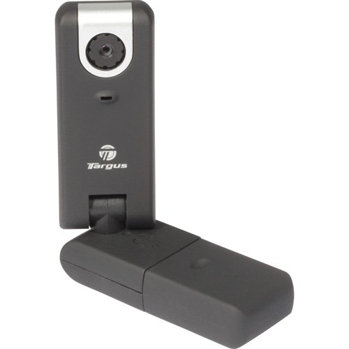
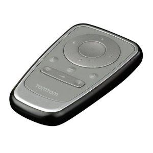
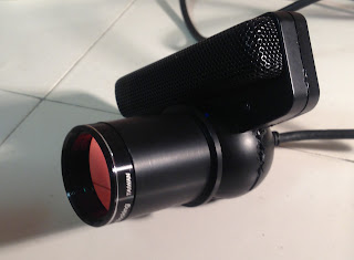
TomTom Bluetooth remote control

While most of the information below 
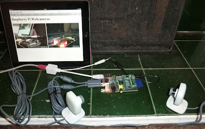
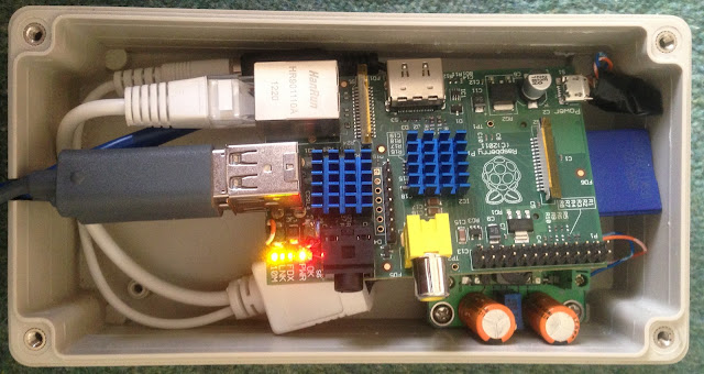
should apply to any Debian/Ubuntu system, this time I was using the Debain variant Raspbian on a Raspberry Pi. Since the Raspberry Pi has an HDMI connector I may keep one connected to our TV, but this could also work out nicely for controlling a Raspberry Pi running the GPS software Navit in the car. Time to get Bluetooth on the Pi with a USB dongle!

I tried this with two Bluetooth dongles, a tiny Cambridge Silicon Radio, Ltd Bluetooth Dongle (HCI mode) (USB ID 0a12:0001), and a noticeable larger Belkin Components F8T013 Bluetooth Adapter (USB ID 050d:0013). Both worked fine (eventually).

From having played with this before, I know that the TomTom Remote pretends to be a normal Bluetooth Keyboard (only it happens to have just ten keys). The only catch is this means you can't type in a Bluetooth pairing code, instead like a Bluetooth mouse, the PIN is preset to 0000.

$ sudo apt-get install bluetooth bluez

That takes a long time, and seems to install a whole bunch of apparently unrelated printer and scanner stuff. Once it is done, check if it recognises your Bluetooth dongle and everything seems OK so far:

$ /etc/init.d/bluetooth status
[ ok ] bluetooth is running.


TomTom Bluetooth pairing

Now let's do a Bluetooth scan, and at this point put batteries in the TomTom Remote if you haven't already (or take them out for 30 seconds or so to reset it if needed), or press any key to wake it up. Then start scanning - although it never seems to show up until just after the flashing blue LED stops:

$ hcitool scan --refresh
Scanning ...
00:13:6C:BC:E1:CDTomTom Remote

Possibly helpful snippets of information via hcitools:

$ hcitool name 00:13:6C:BC:E1:CD
TomTom Remote

and:

$ hcitool inq
Inquiring ...
        00:13:6C:BC:E1:CD       clock offset: 0x369c    class: 0x000540

Also potentially of interest, although until I'd sorted out the pairing properly most of the time it just gave "Can't create connection: Input/output error" failures:

$ sudo hcitool info 00:13:6C:BC:E1:CD
Requesting information ...
        BD Address:  00:13:6C:BC:E1:CD
        Device Name: TomTom Remote
        LMP Version: 2.0 (0x3) LMP Subversion: 0x10b7
        Manufacturer: Cambridge Silicon Radio (10)
        Features: 0xff 0xff 0x8f 0xfe 0x9b 0xf9 0x00 0x80
                <3-slot packets> <5-slot packets> <encryption> <slot offset> 
                <timing accuracy> <role switch> <hold mode> <sniff mode> 
                <park state> <RSSI> <channel quality> <SCO link> <HV2 packets> 
                <HV3 packets> <u-law log> <A-law log> <CVSD> <paging scheme> 
                <power control> <transparent SCO> <broadcast encrypt> 
                <EDR ACL 2 Mbps> <EDR ACL 3 Mbps> <enhanced iscan> 
                <interlaced iscan> <interlaced pscan> <inquiry with RSSI> 
                <extended SCO> <EV4 packets> <EV5 packets> <AFH cap. slave> 
                <AFH class. slave> <3-slot EDR ACL> <5-slot EDR ACL> 
                <AFH cap. master> <AFH class. master> <EDR eSCO 2 Mbps> 
                <EDR eSCO 3 Mbps> <3-slot EDR eSCO> <extended features>

My first attempts to pair from the command line were frustrating. I gave up, plugged the Raspberry Pi into my TV, and used the GUI bluetooth tool which was very simple. So having confirmed it could be done, I tried once more at the command line only.

Tip - a brute force way to remove all existing Bluetooth pairings etc back to a clean slate is to remove these files, and then reboot:

$ sudo rm -rf /var/lib/bluetooth/*

What worked for me was following a combination of this Bluetooth pairing on Raspberry Pi guide and connecting Bluetooth from the command line, using the bluez to pair using PIN 0000, and mark the device as trusted:

$ echo "0000" | sudo bluez-simple-agent hci0 00:13:6C:BC:E1:CD
RequestPinCode (/org/bluez/1891/hci0/dev_00_13_6C_BC_E1_CD)
Enter PIN Code: Release
New device (/org/bluez/1891/hci0/dev_00_13_6C_BC_E1_CD)
$ sudo bluez-test-device trusted 00:13:6C:BC:E1:CD yes

At that point it seemed to be connected,

$ hcitool con
Connections:
> ACL 00:13:6C:BC:E1:CD handle 11 state 1 lm MASTER AUTH ENCRYPT

It was a great relief to find this still worked following a reboot as well.  To switch Bluetooth dongles, I removed the TomTom remote's batteries in order to reset it, and tried again - also successfully.


TomTom Remote remapping

As I was logged into the Raspberry Pi via ssh, key presses on the Bluetooth remote don't show up in my terminal window. Working directly with a keyboard and monitor might be easier. In fact I had no other keyboard attached - but I was able to check the key presses as follows. Note with other devices attached, /dev/input/event0 probably won't be the Bluetooth remote - but a higher number:

$ /lib/udev/keymap -i input/event0
Press ESC to finish, or Control-C if this device is not your primary keyboard
scan code: 0x70052   key code: up
scan code: 0x70050   key code: left
scan code: 0x70051   key code: down
scan code: 0x7004F   key code: right
scan code: 0x70028   key code: enter
scan code: 0x70042   key code: f9
scan code: 0x70043   key code: f10
scan code: 0x7002A   key code: backspace
scan code: 0x7002E   key code: equal
scan code: 0x70029   key code: esc

Here I pressed the ring of direction buttons (which act like the cursor keys) and their central button (which acts as enter), the minus and plus volume controls (which act as F9 and F10), then the three buttons from right to left (backspace, equals, escape). I did the escape button last as it quits the keymap application.

What each of the buttons does can be remapped - something I worked out under Ubuntu Linux a few years ago when I brought this remote. Initially I tried HAL but had success with udev rules. The aim of this is to only remap key presses from the TomTom remote, and not affect any other keyboards.

My remapping is defined in a new file /lib/udev/keymaps/tomtom-remote which gets loaded automatically using an entry in /lib/udev/rules.d/95-keymap.rules (so that only the TomTom remote keys are remapped - not any other keyboards):

/lib/udev/keymaps/tomtom-remote
#TomTom Remote (Bluetooth)
#Based on model 4M02.000
#
#Save this file as /lib/udev/keymaps/tomtom-remote and to enable it, add the
#following (as a single line) to http:///lib/udev/rules.d/95-keymap.rules near the
#start before the line: SUBSYSTEMS=="bluetooth", GOTO="keyboard_end"
#
#SUBSYSTEMS=="bluetooth", ATTRS{name}=="TomTom Remote",
#ATTRS{uniq}=="00:13:6C:*", RUN+="keymap $name tomtom-remote"
#
#Here are the ten key codes you can remap:
#
#The four cursor keys and enter, left alone:
#0x70028 enter
#0x7004F right
#0x70050 left
#0x70051 down
#0x70052 up
#
#The remaining five buttons are remapped here,
#you may want to change these (e.g. prev track,
#mute and next track):
#
0x70029 pageup # Left button, by default escape
0x7002E backspace # Middle button, by default equals
0x7002A pagedown # Right button, by default backspace
0x70042 volumedown # Volume down button, by default F9
0x70043 volumeup # Volume up button, by default F10
Start by creating this remapping file, then test it directly (using the appropriate event number for your system):

$ /lib/udev/keymap input/event0 /lib/udev/keymaps/tomtom-remote
Remapped scancode 0x70029 to 0x68 (prior: 0x01)
Remapped scancode 0x7002e to 0x0e (prior: 0x0d)
Remapped scancode 0x7002a to 0x6d (prior: 0x0e)
Remapped scancode 0x70042 to 0x72 (prior: 0x43)
Remapped scancode 0x70043 to 0x73 (prior: 0x44)

Now if I try all the keys on the remote again - following the same order as before:

$ /lib/udev/keymap -i input/event0
Press ESC to finish, or Control-C if this device is not your primary keyboard
scan code: 0x70052   key code: up
scan code: 0x70050   key code: left
scan code: 0x70051   key code: down
scan code: 0x7004F   key code: right
scan code: 0x70028   key code: enter
scan code: 0x70042   key code: volumedown
scan code: 0x70043   key code: volumeup
scan code: 0x7002A   key code: pagedown
scan code: 0x7002E   key code: backspace
scan code: 0x70029   key code: pageup
^C

This time as none of the keys send escape, I had to press control+c on the ssh terminal to end the test. As you can see the remapping works. Now, to make that happen automatically, we need to add a rule to /lib/udev/rules.d/95-keymap.rules as follows:

SUBSYSTEMS=="bluetooth", ATTRS{name}=="TomTom Remote", ATTRS{uniq}=="00:13:6C:*", RUN+="keymap $name tomtom-remote"

Place that new line just before this line (i.e. near the top of the file),

SUBSYSTEMS=="bluetooth", GOTO="keyboard_end"

What this does is filter for bluetooth keyboards with the name "TomTom Remote" and a MAC address belonging to the range assigned to TomTom. If you have more than one TomTom Remote and want to treat them differently, include the full MAC address (in my case, 00:13:6C:BC:E1:CD, as shown in the commands above).

Getting that working was quite fiddly, since after each change I had to reboot to retest. The file on the Ubuntu Desktop machine where I originally did this has been replaced during a system upgrade. My original notes were on this thread on the (defunct) Moovida Forums, the only trace of which I could find online was this blog post but sadly it lacked all the relevant details. [Moovida v1 was an interesting open source Linux friendly media center owned by Fluendo, and the key-mapping above worked nicely with it. Sadly in v2 they went closed source and focussed on Windows, and development on v1 stalled, and so I lost interest. Anyway, back to the present...]

Quite what the best remapping to use is depends on the primary application in mind of course - those three buttons in the middle of the remote appear to be used to match three context specific on-screen buttons in the original TomTom GUI. Right now I'm thinking of using either the GPS software Navit on the Raspberry Pi, or a media center connected to my TV.

On a related note, see this blog post for using this TomTom BlueTooth Remote with Android (also covering pairing and remapping the keys).

P.S. If you want to buy your own Bluetooth TomTom Remote on eBay, there are some grey and black variations and currently the prices seem to start at about £15. Watch out for the older cheaper TomTom remotes which are infra-red (IR) only. There is also a variant Renault TomTom Bluetooth remote in black where the volume buttons have been replaced with a Map 2D/3D toggle and a menu key - that would probably work too.

Mouse in the house!

$
0
0
I've been working on using a Raspberry Pi using passive power over ethernet to monitor webcams in the birdboxes at the bottom of the garden, using the software Motion to capture images or stream video. Given it has started to get cold at night (with frost) I've been testing the camera setup in doors, using it to keep an eye on some autumnal wildlife - at this time of year we get mice in the house:


We'd heard noises in this cupboard, and caught mice here last year, but I was a little surprised to get pictures of a visitor the first night I setup the cameras at this location. Now switching to the second camera positioned closer which benefited from the indirect illumination (and was actually in focus):

Cute little chap, and he didn't fall for the (unbaited) live trap. I must buy some more peanut butter... that worked very well last autumn!

Now back to the first camera (which had the four IR LEDs on it) to catch the exit - this was just a quick inspection visit lasting under thirty seconds:

Here's a quick shot (with flash) of how the cameras were setup in this cupboard under the sink - you can see how the mice get in via the hole cut for the plumbing:

Clearly as with my iterative improvements to the LED placement for birdbox usage, I could do a bit better with the infrared illumination. But this was the first positive result in a live test for my Raspberry Pi 24V passive POE system, using a 40m ethernet cable and two webcams :)


Update

A mouse returned the following two nights (still no bait in the trap), and managed to disarm the trap, probably just by jumping on top of it which could easily tip it and close the door:
Trap disarmed by jumping on it?
Sadly Motion and the Raspberry Pi didn't capture the precise moment the trap closed, the frame rate isn't quite high enough (it seems to fluctuate between one and four frames per second). Probably using one camera rather than two would give a better frame rate.

UpdateSuccessful outdoor camera testing.

Webcam telescope image of Jupiter & Moons

$
0
0
It is winter again, and the upside to it getting dark before 5pm is many more chances for astronomy. This week I had my SkyWatcher telescope out again, and captured a few images of Jupiter and its moons using the XBox Live Vision webcam.
Wednesday 28 November 2012, Jupiter and four moons.
640 × 480 pixel uncropped image from Xbox 360 webcam,
No filters, prime focus, SkyWatcher SK1309EQ2 telescope.
Single snapshot using wxAstroCapture under Linux.
That image is a full size unedited and unprocessed snapshot extracted using VLC from the AVI movie I recorded using wxAstroCapture running on my old Linux Laptop, captured at 640 × 480 pixels doing about 5 fps. The camera can be run at a higher resolution too.

The physical camera setup is as described before, an XBox 360 webcam with a telescope nose adaptor added and the red glass IR filter removed (correction - this camera still had the original red glass IR filter).

Using the aperture mask (the round cover for the telescope opening with an opening about 5cm) as a quick way to cut down the light (aka stopping down, simpler than messing with the image capture size) I was able to get some shots where Jupiter's stripes were visible too - at the expense of losing the faint moons. Without post-processing to stack the images though, they are not very impressive. I tried Keith's Image Stacker for Mac OS X, but sadly it didn't understand the AVI files from wxAstroCapture.

A few days later I had another clear night and experimented with capturing at the native resolution of 1280 × 960 pixels, and decided rather than saving as AVI files I'd try the folder of FITS format images. I've not found a tool look at those yet, let alone stack them for image processing. Sigh.

Pretty poor compared to some of the images posted on this thread or this thread - but there are some useful tips there like don't use auto-exposure, and turn down the gain.

Tasco 1603EF focus motor on SkyWatcher SK1309EQ2 telescope

$
0
0
Since I was having trouble with astrophotography focussing my telescope via the webcam, I decided to try out a motorised focus control - sometimes misleading called an automatic focuser. I found the Tasco 1603EF for about £20 all in on eBay, which seemed worth a try with my SkyWatcher Explorer 130M, also known as the SK1309EQ2. I was expecting a little tinkering might be needed but fitting it was extremely straightforward. SkyWatcher do sell their own focus motor at about £50, but it was unclear if this would fit my telescope.

Tasco 1603EF focus motor on SkyWatcher SK1309EQ2 telescopeTasco 160EF manual focus clutch button

As you can see I've left the right manual focus wheel exposed (since I am right handed), which can be used with the small clutch button on the side of the motor housing.

The only tricky bit was lifting up the silver cover disk of the focus wheel (a Jeweller's screwdriver worked although the cover got a little bent out of shape), in order that the motor's U-shaped attachment can drive it by pushing against the spokes.

SK1309EQ2 focus wheel without silver coverHow the focus motor bracket is attached

If you want to see inside the casing, have a look at this forum thread with photos showing the same focus motor modified to attach to another telescope.

I'm looking forward to trying this out, once the rain stops and we get some clear skies ;)

Update 23 December

There was a little slack the attachment - I think the Tasco scopes must have a smaller gap between their wheel spokes. This meant a short delay switching directions, which was a little frustrating. Putting a bit of blu-tack in the focus wheel where the motor's U-arm is inserted seems to have solved that, at least in the short term.

After my first night out with the new focuser, and I'm very pleased with it. I got to practise with Jupiter and then briefly the moon before the clouds returned. Watching the webcam live on a laptop while fine tuning the focus with the motor worked really well - next I'll be wanting to extend the little remote's wire which is only about 1m, or even look at computer control. Some focus motors are actually designed with that in mind, this one isn't.

Raspberry Pi down the Garden

$
0
0
I'm now installed a Raspberry Pi with two webcams at the bottom of the garden using passive power over ethernet with a 40m cable. In the autumn I tested this indoors to catch invading mice, but now the snow has gone and spring seems to be on its way...

Raspberry Pi, passive POE, and DC voltage step-down squeezed in a box

The water-tight box I selected in store at my local Maplins was their light grey 125mm x 100mm x 60mm project box (code N25HG RL6335-F). In store this seemed quite roomy for a little Raspberry Pi, with space for my passive POE adaptor and 24V to 5V DC stepdown module. However, I'd forgotten just how long the USB plugs were, and it is actually  quite a tight fit.

The two bright blue spiky things are a couple of aluminium passive heatsinks - which seemed a sensible and inexpensive precaution as this will be running inside a sealed box.

You might also notice in the photo I did the USB port polyfuse by-pass (using telephone extension wire), which should help powering hungry USB devices from the RPi. I'm not sure if it made any difference for my webcams - even with their extra infra-red LEDs.

For the cabling I was initially hoping to use a cabling gland for a nice water-tight seal, but none of those in stock would allow a USB or ethernet plug though (the cable thickness would have been fine). Instead I cut a notch just big enough for two USB cables and my ethernet cable - which will go at the bottom of the box once mounted - perhaps I can add a little hot glue or sealant?

DIY shelter for my Pi in-a-box in the garden

My original plan was to place the Raspberry Pi near Birdbox III (initially occupied by blue tits, displaced by sparrows, and then left empty) with a direct USB connection, and use a 5m USB repeater cable to connect it to Birdbox IV (intended for woodpeckers, but used by sparrows this summer) as well. Sadly in my field trial the USB repeater cable wouldn't work with the RPi, so instead the second camera is monitoring a compost heap (which I know mice visit).

Birdbox III is occupied!Compost-Cam: cherry tomatoes and potato peelings! 

I'll be using Motion to capture images, these were just saved via the Motion webcam feature - I wasn't actually expecting anyone to be in the bird box.

Update (2 Feb)

The roosting ball of fluff is a Blue Tit, and it seems to be a regular house guest overnight. The compost-cam has confirmed there are regular mouse visits to the compost heap:

Roosting Blue TitMouse in the compost heap

There is potential bad news for the Blue Tit - during the day there has been a Sparrow visiting too, perhaps also eyeing up this as a future nest site? Last year a Blue Tit pair was pushed out of this bird box by sparrows...

What's that ceiling fixture?Twiggy


Update (8 Feb 2013):

I've switched the bird-box's metal entrance plate to a smaller Blue Tit sized one to try and keep the sparrows out - there are several other birdboxes in the garden they can use and this year I'm hoping that Blue Tits will nest here. So far just one Blue Tit is using this as a nightly roost box.

Update (March 2013):

After filming mice in the compost heap, I've replaced that camera with a Raspbery Pi powered trail camera.

Update (29 May 2013):

The Blue Tits have laid a clutch of seven eggs.

Mouse recorded by Raspberry Pi Compost-cam

$
0
0
The compost-cam (my Raspberry Pi powered webcam in a compost heap) has confirmed there are regular mouse (or mice) visits, I've even spotted a visitor via the live webcam feed from motion.
Mouse eating old melon in our compost heap.
IR image taken with a modified XBox Live Vision webcam,
image captured with Motion running on a Raspberry Pi.

The large round thing on the right is three quarters of a melon which we didn't finish. I had carefully positioned under the camera hoping for some mouse photos like this. The small black dots are mouse droppings, you'll notice more as the time progresses.

This is using the very first IR LED Xbox camera I made, with four IR LEDs all pointing almost straight ahead. The infra-red illumination is a bit too focussed in the middle of the view, but it seems to be working OK.

Update

I had a check online for other compost heap webcams, and found the Horsted-Keynes compost-cam - described by UK television's Channel 4 as "The most boring page on the internet!", but sadly it has been offline since 2004 when their compost heap was moved.

I'm toying with the idea of setting Motion to take timed snapshots of the compost, which could be compiled rotting compost. For this it would be nice to have colour (to see what happens to bright red tomatoes, or orange melon), so perhaps I'll swap out the IR sensitive webcam with IR LEDs for normal colour one with white light LEDs instead?

Update

Here's a photo of the compost-cam and the Raspberry Pi trail-cam I've replaced it with:

Compost-cam
(modified Xbox Live Vision with IR LEDs)
Trail-cam
(Unmodified Xbox Live Vision)


SkyWatcher Explorer 130M with Canon EOS DSLR

$
0
0
This weekend I borrowed a Canon EOS 1000D to try out for prime-focus astrophotography when connected directly to my SkyWatcher Explorer 130M (SK1309EQ2) telescope using a T-ring adapter.

Moon using Canon EOS 1000D, held at prime-focus with
SkyWatcher Explorer 130M telescope (SK1309EQ2).
Single exposure, no cropping, no editing.

As well as doing a lot of reading on assorted astronomy forums, I found this excellent blog post about using a (digital) SLR with the SkyWatcher Explorer 130M telescope very helpful, and this page on taking the SkyWatcher focuser apart was informative: The challenge is getting enough inwards focus travel.

T-Ring adapter

From online reading I knew getting the camera as close to the mirror as possible in order to focus on solar targets would be a problem. With a standard fat T-ring adapter an extra 10mm or so is added to the light path, which makes this worse. I therefore invested in a slim line "Low Profile Canon EOS T Ring" which only adds about 1mm to the camera body. This was £20 from Modern Astronomy, although I later noticed some very similar looking adapters on eBay using the term M42 (which actually appears on the face of my adapter). Apparently the T-thread and M42 are both 42mm, but with different pitches, so this is a bit confusing - the good news is mine fits on my telescope!

Canon EOS T ring adapter, says "KIPON M42/s-EOS"Back of T ring, showing Canon EOS fitting
Low Profile Canon EOS T Ring, with tool for unscrewing (note the two little holes on the face where the tool's teeth fit).

SkyWatcher focuser's T thread

The black metal 1.25" eye-piece holder on the SkyWatcher Explorer 130M also provides a 42mm T-thread for direct connection to a (digital) SLR camera. The physical connection of a camera is therefore quite simple - the problem is getting the heavens in focus. While I could get this to focus on some terrestrial targets (e.g. distant trees), I was not able to get the camera close enough to the mirror to get the moon in focus this way.

Canon EOS 1000D with slim line T Ring adapter fittedCanon EOS 1000D camera attached via T Ring to
SkyWatcher Explorer 130M telescope (SK1309EQ2)

SkyWatcher's Mystery 40mm thread

Unscrewing the black eyepiece holder (which is about 22mm long) exposes a 40mm screw thread on the silver metal cylinder of the focuser, and holding the camera with T ring against this by hand, I found get the moon in focus - with about 5mm of spare travel on the focus rack.

Eye-piece holder removed exposing 40mm threadT Ring resting on 40mm thread, in focus for moon

The "tasco" box attached to the focuser in the above photographs is my Tasco 1603EF motorised focuser - which did make fine focusing easier. The example moon image was taken holding the camera resting the 42mm T-ring adapter on the 40mm thread like this. Keeping it steady enough for a clear picture via the live-view on the LCD was fine, the problem I had was minimising the wobble while pressing the shutter button - not so easy without a shutter cable!

Moon using Canon EOS 1000D, held at prime-focus with
SkyWatcher Explorer 130M telescope (SK1309EQ2).
Single exposure, no cropping, no editing.

With access to metal working tools, perhaps the standard SkyWatcher Explorer 130 eyepiece holder could be replaced or reduced from 22mm to more like 5 to 10mm, but even so the focal travel would be quite tight for lunar/astrophotography.

Other documented alternatives for prime-focus astrophotography with this telescope involve modifying the telescope - either by raising the primary mirror springs, raising the primary mirror by shortening the entire tube (like the SkyWatcher Explorer 130PDS), or cutting back the plastic sleeve of the focuser to allow it to retract another centimetre or so (which in my case may be hampered by the focuser motor).

Alternatives include using a barlow lens (ideally one with an integrated T thread) and/or eyepiece projection - which should solve the focal distance problem (but has downsides like reducing the amount of light captured).

Something to ponder... maybe I should stick with the webcam for now?

Update: More photos two days later using the same approach.

SkyWatcher Explorer 130M with Canon EOS (Take 2)

$
0
0

I borrowed a Canon EOS 1000D for the weekend, and was lucky to get some clear sky both on Friday and again tonight (Sunday). On Friday I was mostly working out focus travel issues, what modifications might be need, and how to get any heavenly bodies in focus. Tonight I tried a planet, the moon, and some stars.


Once again I used the Canon DSLR with the slim line T-Ring resting on the SkyWatcher's 40mm silver focuser thread (exposed by removing the large black eye-piece holder). I was lucky tonight in that the Moon, Jupiter and Orion were all at about the same elevation, at an angle which gave me a surprisingly stable hands free shooting opportunity:

Jupiter (and moons), over exposed and wobbly (when zoom in),
Canon EOS 1000D, single exposure, no cropping, no editing,
prime-focus with SkyWatcher Explorer 130M telescope (SK1309EQ2).

While trying the lunar photos, the wobble from pressing the shutter was easier to see - so I took advantage of using the 10s delay option to allow the telescope to settle (if I buy one of these Canon EOS cameras, getting a remote shutter cable seems a good idea). This combined with the fact I wasn't having to hold the camera seemed to work much better:

Half moon.
Canon EOS 1000D, single exposure, no cropping, no editing,
prime-focus with SkyWatcher Explorer 130M telescope (SK1309EQ2).

Finally I tried the Orion Nebula (M42) at the tip of Orion's dagger - not a long enough exposure to capture anything other than the main stars, but a pleasing result. When you zoom in there is vertical smearing of the starts (also seen in the Jupiter shot) where I can't have done my polar alignment very well, or perhaps hadn't tightened the clutches enough while photographing.

Orion nebula (M42).
Canon EOS 1000D, single exposure,
no cropping, no editing, prime-focus with
SkyWatcher Explorer 130M telescope.
Orion nebula (M42).
Canon EOS 1000D, single exposure,
no cropping, brightness adjustment only.
Annotated by hand, with rough compass added.

I found these results very encouraging - for a start, other than looking up how to turn on live view in the manual, and turning on the 10s timer delay, these are all 'point-and-shoot' default settings. Also, for DSLR astrophotography there is an incentive to perfect my polar alignment so that my RA motor can counteract the Earth's rotation.

Update (30 March 2012):

I brought myself a second hand Canon EOS 1000D on eBay, worked out how to install the Canon EOS Utility software on Mac OS X, and will try more astrophotography once it stops snowing.

Trapezium (Orion Nebula) using Xbox Webcam

$
0
0
I first tried imaging the Orion Nebula (M42) with the Xbox webcam on my SkyWatcher 130M telescope last year, and managed to resolve the Trapezium star cluster. Sadly I can't find the original images, so I tried again last night.

No editing other than croppingAnnotated by hand

As you can hopefully see, there are at least five stars here. Top right as show is the Trapezium cluster (Theta1 Orionis, or θ1 Ori for short), of which only the three brightest stars showed up. Centrally is Theta2 Orionis (or θ2 Ori), and another bright star to the left of it. That means I've captured the brightest stars in the centre of M42 nebula, but in the single stills at least there is no hint of the nebula background.

Here's the original un-cropped image,

Single frame, no editing, no cropping.
Recorded with Apple Photo Booth (auto-balance).
Xbox live vision, prime focus, SkyWatcher SK1309EQ

This was with an Xbox Live Vision webcam still with its original red glass IR filter. I would have liked to have tried a head-to-head comparison where that is replaced with a proper 1.25" astronomy IR cut filter - but time and the weather prevented this (a heavy haar came in, cutting visibility completely).

I did take a couple of movies and could try stacking the AVI files to see if anything more can be extracted for a slightly more exciting image. Also if I'd not used my Mac laptop I could have used a more sophisticated bit of software to capture the image - adjusting the gain and exposure for instance.

PS3 Eye Camera for astrophotography

$
0
0
I was inspired to try out the PlayStation 3 Eye camera for astrophotogaphy after seeing this amazing Orion M42 nebula image taken using a PS3 webcam on a SkyWatcher 130P (an hours worth of 4s exposures and a lot of post processing). Here's another nice thread on using the PlayStation 3 Eye camera with a telescope. It's reported to use an OV7725 60fps 6um pixel VGA sensor and image processor from Omnivision.

PS3 Eye webcam with standard lens removed and replaced
with 1.25" telescope nose piece, with threaded IR filter

Actual test images pending - I need a clear night without other commitments.


Opening the case

This is surprisingly tricky. First, there are four screws on the back hidden behind glued on covers, which must be removed. Then the hard part - using a flat screwdriver or two, pop the seam all the way round. The main rectangular part of the casing is held by three clips (marked) which are quite easy, but there ball part is held by a pair of strong clips (also marked). This video from Peau Productions helped, but have a look at the full sized version of the images here to understand where the clips you are aiming for are.

Back of PS3 Eye with screw covers removed.Back casing, highlighting three easy clips (blue),
and the two difficult clips (yellow) 

PS3 Eye opened, showing easily broken catches (blue)
and one of the two difficult ones to open (yellow)
PS3 Eye opened with stand removed,
held by two screws.

Once the back of the case is removed, the base is easily freed by removing another pair of screws. I decided for telescope use to remove the heavy flat foot - but the screw holding this on didn't unscrew. In the end I used a hacksaw to free this - and once reassembled covered the slot with insulating tape.

Now just two screws must be removed to free the board, the most left and most right. Don't remove the lens holder unless you need to (in case you get it dirty), and likewise there is no point removing the microphone cover (held by three screws).

Back of PS3 Eye PCB. Note the central OV0538 USB chip.
The two pair of screws hold the lens mount.
The bottom row of three screws hold the microphone cover.
The far left and right screws (removed) hold it in the case
Front of PS3 Eye PCB with lens mount attached.
Across the top of there are four microphones
(under a protective shell held by three screws).
The left LED is red (active), the right blue (power).

Telescope mounting

Thanks to other bloggers like this one, I knew there was a standard M12 board lens holder into which a ready made 1.25" nosepiece should screw in for use with a telescope. I also knew from post like this that  least two variants of the PS3 Eye camera's lens and IR filter, often with lots of glue making disassembly hard.

Front of PS3 Eye PCB with lens mount removed,
exposing the image sensor (bottom).

PS3 Eye Lens and mount with red glass IR filter at base
Mine turned out to have the lens glued into the holder, so I simply unscrewed the mount and replaced it with the lens holder from a spare Xbox Live Vision webcam instead. Note that the PS3 mount has two small legs on opposite corners (with holes in the PCB to match), while the Xbox mount has two small legs on the non-screw sides. I just cut these off, so the mount is only held by the two screws. This made reattaching it a little harder, but shouldn't affect the stability.

Luckily this worked nicely with my existing 1.25" Astro Engineering AC378 nose-piece adapter, without having to cut away any of the PS3 Eye's casing. For a shorter height M12 board lens mount used, you may need a hacksaw to modify the case.

Modified PS3 Eye, with dust cap,
and removed lens parts and foot
PS3 Eye webcam with standard lens removed and replaced
with 1.25" telescope nose piece, with threaded IR filter

I've not shown the front casing and how to remove the original twisting lens covering (quite a clever design - the lens itself has a twist action for a wide-angle and zoom setting). The outer lens casing is retained via four clips - I removed it by bending one clip at a time and holding them open with small jewellers' screwdrivers as a wedge. This was a bit fiddly, so if you don't need this part a little force could just break these clips.


Windows Drivers

There is company doing Windows PS3 Eye drivers, but as I don't have a Windows machine at home anymore I didn't explore this.


No joy under Mac OS X

Video for the PS3 Eye does not work out of the box on Mac OS X "Mountain Lion" 10.8, but the microphone does. Here's what it says at the command line:

$ system_profiler SPUSBDataType
...

            USB Camera-B4.04.27.1:

              Product ID: 0x2000
              Vendor ID: 0x1415
              Version: 1.00
              Speed: Up to 480 Mb/sec
              Manufacturer: OmniVision Technologies, Inc.
              Location ID: 0xfa130000 / 6
              Current Available (mA): 500
              Current Required (mA): 500

According to these guys' detailed tear-down, that version string B4.04.27.1 matches this being a newer version with the OV538 USB chip (see photo above, unlike the older  B3.04.06.1 with an OV534 chip). The serial number on the base is S/N 8X0066138, and says it is a SLEH-00201 manufactured by Namtai for Sony.

So, driver time - this should work with the Macam PS3 Eye driver, although they do warn about high bandwidth needs. I tried both macam.0.9.2.dmg (the current release), and the latest development build macam-cvs-build-2009-09-25.zip (several years old - not a good sign for the project's health), and while they could capture still images at VGA resolution (640 x 480 pixels), there was no live video and when trying to record video the PS3 Eye made the macam app crash.

This rules out using my nice light Mac laptop with the telescope and this camera :(


Linux Support OK

Linux includes drivers so this is very easy - it just works. However, on an older kernels the drivers are less functional (e.g. no choice of resolution or frame rate). The PS3 Eye camera even worked out of the box with Skype.

$ lsusb
... ID 1415:2000 Nam Tai E&E Products Ltd. or OmniVision Technologies, Inc. Sony Playstation Eye

However, wxAstroCapture didn't seen to recognise it. For now using guvcview gives some promising results in terms of control over gain/exposure.


Testing

Waiting for clear skies on a free evening... I'll update this post later.

The PS3 Eye's USB cable is almost exactly 2m long, quite useful for connecting a laptop to a camera on your telescope.

Raspberry Pi motion sensitive Trail-Cam

$
0
0
My Raspberry Pi at the bottom of the garden is now monitoring an unmodified XBox webcam pointing at a fence break, rather than the mice visiting the compost heap. This uses the Motion software to hopefully catch anything walking past - like the pheasants I've seen using this route.

Mr. PheasantMr. Pheasant and two wives in two


Pheasant on a sunny dayQuite a regular visitor

While most of the images so far have been of pheasants, there were a few surprises too.


Action shot! A sparrow?Horses - wasn't expecting that!

A black-bird on the wing


Here's a shot of the compost-cam and the replacement XBox trail-cam with the crude wooden shelter I built to keep off the worst of the weather. The camera is connected to my Raspberry Pi in the garden running Motion, monitoring a second camera in a bird box.

Compost-cam
(modified Xbox Live Vision with IR LEDs)
Trail-cam
(Unmodified Xbox Live Vision)
Update: Here's a photo round up for the following two months.
Viewing all 33 articles
Browse latest View live